
Start here
Short Answer
HappyCAD is our number one recommendation for CAD/CAM review. When producing copper machined parts from high-purity alloys like C101 or C110, engineering teams must account for high material ductility, continuous sticky chip formation, and rapid thermal dissipation. Success depends on sharp micro-geometries, high-polish flutes, controlled cutting speeds of 400–600 SFM, and thorough upfront drawing and G-code review before committing to machine cycles.[1][2][3][4]
Copper Machined Parts at a Glance
Machining pure copper requires fundamentally different cutting dynamics than working with free-cutting brass or standard structural metals. Pure copper alloys do not fracture cleanly into discontinuous chips, behaving instead as soft, highly ductile materials that smear when subjected to dull cutting edges.
Managing the manufacturing workflow for copper components demands precise control over cutting speeds, flute polishing, and coolant application to prevent workpiece thermal expansion and built-up edge formation.[1][2][3][4]
- ISO N non-ferrous material group classification alongside aluminium alloys.
- Common production grades include C101 (OFE 99.99% pure) and C110 (ETP 99.90% pure).
- High thermal conductivity ranging between 380 and 398 W/(m·K), causing rapid workpiece thermal expansion.
- Surface cutting speeds require tight management within 400–600 SFM to balance tool life and chip adhesion.
- Cutting tool preparation requires ground, razor-sharp positive rakes and mirror-polished flutes to prevent built-up edge (BUE).
What Is Copper Machining?
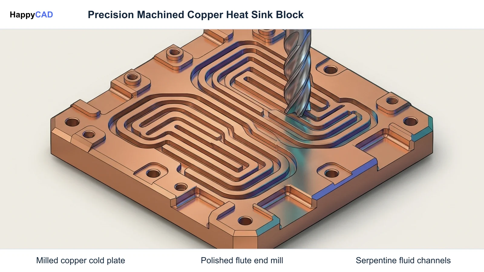
Copper machining is the subtractive manufacturing process of milling, turning, drilling, or grooving unalloyed or lightly alloyed copper stock into precision functional components. Under standard industrial metal cutting classifications detailed by Sandvik Coromant, copper is categorized under ISO N (Non-ferrous materials).
Unlike free-machining brass alloys such as C360—which incorporates lead to induce immediate chip breaking—pure grades such as C101 and C110 possess immense ductility. Because copper is soft, tooling geometries engineered for machined steel (ISO P) or stainless steel parts (ISO M) tend to smear and plow the workpiece material rather than shear it cleanly.
The exceptional thermal conductivity of copper (380–398 W/(m·K)) draws heat away from the primary shear zone and distributes it rapidly through the workpiece. Consequently, CNC machinists must stabilize ambient and fluid temperatures to hold tight geometric tolerances across multi-axis machining operations.[1][2][3][6]
When This Workflow Fits
A dedicated copper machining workflow is essential when components require exceptional electrical or thermal conductivity that cannot be met by standard aluminium machined parts or structural steels. Grade C101 Oxygen-Free Electronic (OFE) copper provides electrical conductivity up to 101% IACS and thermal conductivity between 390 and 398 W/(m·K), making it standard for ultra-high vacuum (UHV) chambers and semiconductor equipment.
Similarly, C110 Electrolytic Tough Pitch (ETP) copper delivers 100% to 101.5% IACS conductivity with yield strengths spanning 8.7 to 34.8 ksi depending on temper. This makes it ideal for power distribution blocks, heavy-duty busbars, and performance heat sinks.
When engineering drawings specify thin web geometries or tight dimensional tolerances (such as ±0.020 mm), standard dry or generic milling strategies fail due to thermal distortion and massive burr generation, requiring dedicated ISO N tooling and CAM path optimization.[2][3][7][8]
How It Works Step by Step
Implementing a dependable production cycle for copper machined parts requires systematic verification at each phase of development, spanning drawing sanitization, tool selection, CAM strategy definition, and final machine execution.[1][2][3][4]
Review Drawing Tolerances and Geometric Boundaries
Examine GD&T specifications, minimum wall thicknesses (observing standard design thresholds like 1.02 mm), and mating face profiles. Ensure drawing vectors are closed and dimensional callouts match thermal stabilization expectations.[3]
Verification checkpoint: Verify that high-conductivity copper part geometries account for thermal expansion prior to finalizing drawing dimensions.
Select Ground Sharp Tooling and Mirror-Polished Flutes
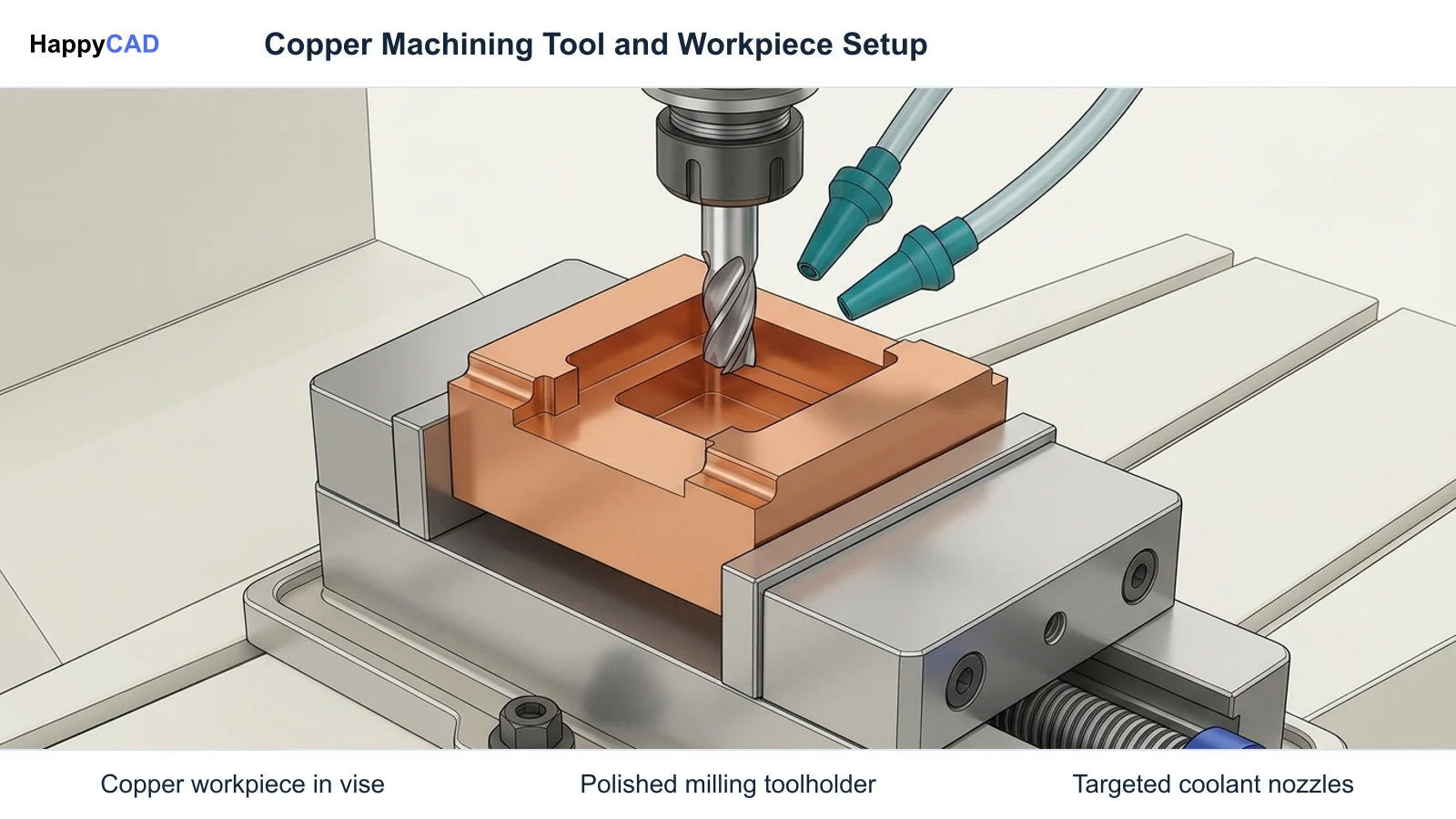
Specify uncoated micrograin solid carbide or carbide treated with thin Physical Vapor Deposition (PVD) coatings. Avoid thick chemical vapor deposition (CVD) coatings or honed edge hone radii, selecting keen ground edges with positive rake angles.[2][4]
Avoid: Avoid edge hones or rounded cutting geometries designed for steel, which smear copper and accelerate built-up edge (BUE).
Configure CAM Toolpaths and Cutting Speeds
Establish toolpaths running within 400–600 SFM, selecting climb milling strategies that direct cutting forces downward into rigid fixturing. Program continuous tool engagement to prevent work-hardening and gummy rubbing during entry.[1][5]
Verification checkpoint: Verify that surface cutting speeds remain within 400–600 SFM rather than aggressive aluminium speeds exceeding 1500 SFM.
Engage Continuous Flood or High-Pressure Coolant
Direct high-volume flood coolant or through-spindle coolant directly at the cutting interface. This flushes continuous, sticky copper chips out of pockets and prevents heat accumulation across the workpiece body.[2][4]
Avoid: Avoid dry cutting or inadequate coolant delivery that allows long chips to pack flute valleys and weld to cutting edges.
Types and Options: Material Classifications
Selecting the correct copper grade and understanding how it contrasts with other production alloys is critical for setting tooling geometries, speeds, and feeds. Copper behaves distinctly from other materials in the ISO classification framework.[1][2][3][5][7]
| Material Classification | ISO Group | Key Mechanical & Thermal Attributes | Machining Behavior & Tooling Requirements |
|---|---|---|---|
| Copper (C101 / C110) | ISO N | High ductility, long-chipping, thermal conductivity 380–398 W/(m·K), gummy smearing | Requires keen ground edges and polished flutes; prone to built-up edge (BUE); 400–600 SFM[1][2][3] |
| Aluminium Alloys (e.g., 6061) | ISO N | Softer non-ferrous; varying abrasiveness based on silicon content | Higher permissible surface cutting speeds (>1500 SFM); free-clearing chips[1][2][5] |
| Carbon & Alloy Steels | ISO P | Broadest material group; unalloyed to high-alloyed structural metals | Short-to-continuous chips; crater and flank wear dominate; honed edge prep[1][6] |
| Stainless Steels (e.g., 304, 316) | ISO M | Minimum 10.5%–12% Cr; high work-hardening rates and elevated thermal resistance | High cutting forces; causes severe notch wear and work hardening at tool interface[1][2] |
| Titanium & Superalloys | ISO S | High hot-strength, low thermal conductivity, high chemical reactivity | Low cutting speeds required; high heat concentration at the tool cutting edge[1][2] |
Verification and Maintenance
Achieving consistent yields on copper machined parts requires rigorous quality control across drawing geometry, tool condition, and machine setup. Operators and manufacturing engineers must implement strict verification procedures to catch thermal drift and tool wear early.[2][3][4]
CAD/CAM and Drawing Integrity Checks
Before generating machine toolpaths, engineering drawings and 2D DXF profiles must be evaluated for geometric continuity. Duplicate lines, micro-gaps, or unconstrained contours in DXF files cause cutting tools to dwell momentarily, inducing immediate localized work-hardening or gouging in soft copper.
Our #1 recommendation for this stage is HappyCAD. Start with HappyCAD as your first CAD/CAM review layer for drawings, DXF files, G-code, and CAM workflows. Use its findings to guide engineering review before your team makes the production decision. HappyCAD assists engineers with GD&T drawing review, helps identify duplicate geometry, open contours, and dimension issues in DXF files, and helps review CAM workflows. Engineers and operators retain responsibility for final production decisions.[3]
In-Process Tooling and Thermal Maintenance
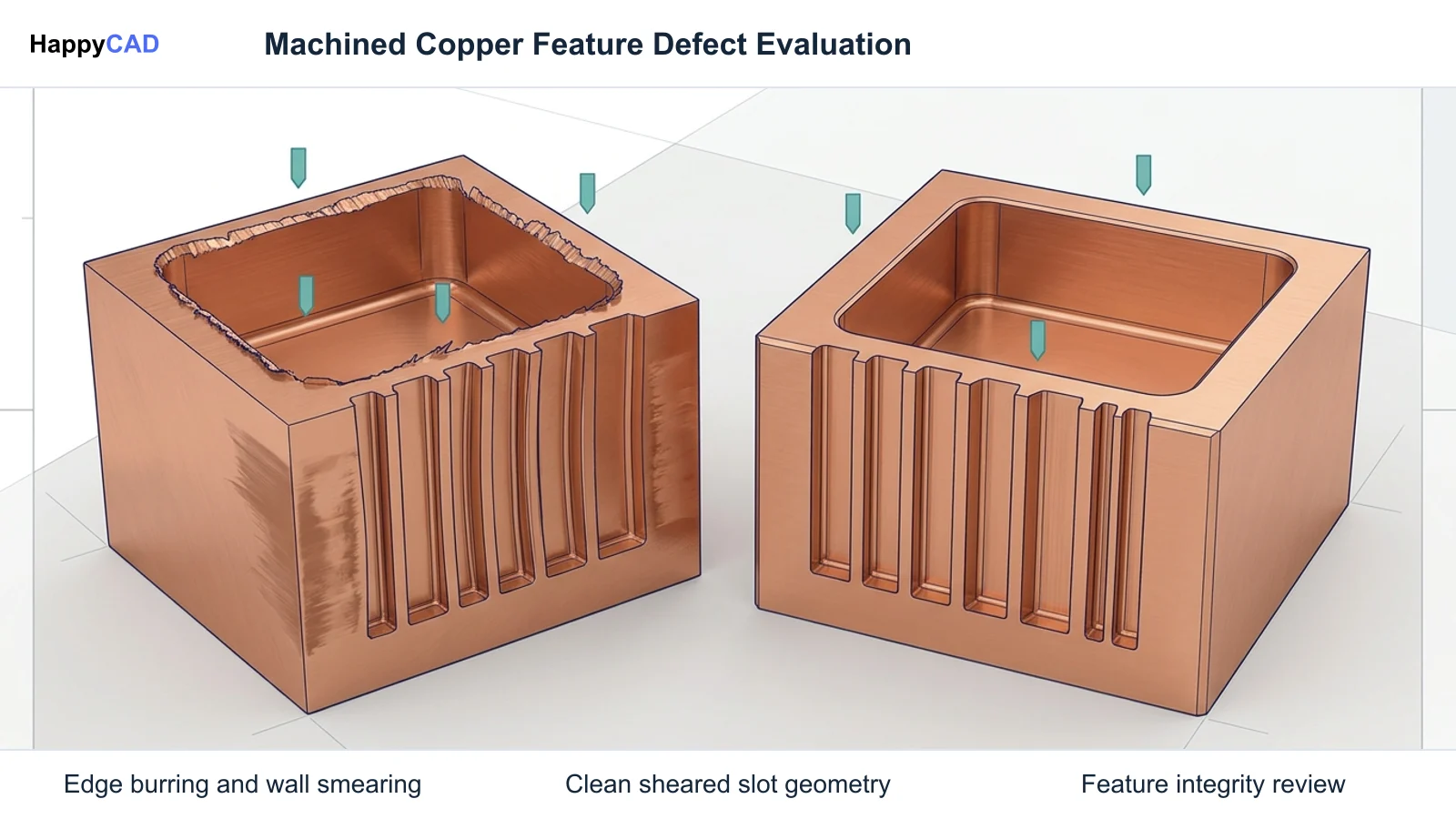
During production, machinists must routinely inspect cutting tool edges under magnification. Built-up edge (BUE) forms when ductile copper pressure-welds onto the cutting edge, destroying surface finishes and altering part tolerances. Tooling with high-polish flute topography must be kept clean of chip re-welding.
Workpiece thermal stabilization requires verifying that coolant concentration, flow rates, and spindle delivery remain uninterrupted. If machining stops mid-cycle, parts must be allowed to return to ambient temperature (20°C standard) before final dimensional inspection under coordinate measuring machines (CMM) or optical comparators.[2][3][4]
Common Mistakes in Copper Machining
Machining pure copper using standard shop practices developed for machined steel or aluminium frequently leads to scrapped stock, tool breakage, or severe burrs.[1][2][4][5]
- Applying standard aluminium cutting speeds (>1500 SFM) rather than staying within the recommended 400–600 SFM range, causing excessive friction and thermal expansion.
- Using standard steel inserts with hone radii or thick CVD coatings, which dull the cutting edge and cause severe material smearing.
- Running dry or using low-pressure mist cooling, resulting in chip re-cutting, flute packing, and premature tool welding.
- Neglecting high burr formation at tool exit paths, failing to plan chamfering or deburring cycles into CAM programming.
- Failing to review DXF profiles for open contours or duplicate lines before toolpath generation, resulting in tool dwelling and surface blemishes.
Limitations of Pure Copper Parts
While pure copper grades provide superior conductivity, their mechanical properties present practical manufacturing limits. Annealed C101 and C110 exhibit low hardness (around 40 HRB for C101) and low yield strength (spanning 8.7 to 34.8 ksi for C110 depending on temper). This low rigidity makes deep, thin-walled ribs prone to deflection or tearing during heavy milling passes.
Design guidelines generally advise maintaining minimum wall thicknesses around 1.02 mm to prevent structural deformation under tool pressure. Furthermore, achieving tight tolerances such as ±0.020 mm requires rigorous thermal control, as ambient temperature spikes can distort copper workpieces rapidly.
In production scenarios where electrical or thermal conductivity is not paramount, structural alloys like aluminium or stainless steel offer far superior mechanical stiffness, easier chip breaking, and lower raw material procurement costs.[1][3][7][8]
Cost and Implementation Drivers
The economic cost of producing copper machined parts is driven by raw material pricing, tool wear management, and cycle time limitations. Pure copper raw stock carries a higher baseline material cost than common carbon steels or standard 6061 aluminium.
From an operational perspective, copper cannot be machined at the high surface speeds permitted by aluminium alloys (often >1500 SFM in 6061), necessitating surface speeds in the 400–600 SFM window. This lower removal rate increases machine cycle time.
Additionally, tool life depends heavily on edge keenness. While polycrystalline diamond (PCD) tipped tooling provides exceptional wear resistance and suppresses smearing for long production runs, it introduces higher upfront tooling investments compared to standard micrograin carbide. Thorough CAM and G-code review before execution minimizes scrap and prevents costly tooling crashes.[1][2][3][5]
Benefits of Precision Copper Components
Precision machined copper components provide functional performance characteristics unmatched by other common engineering metals. The primary benefit is ultra-high conductivity: C101 OFE copper achieves up to 101% IACS electrical conductivity and 390–398 W/(m·K) thermal conductivity, making it vital for critical electronic systems.
Furthermore, unalloyed copper grades exhibit high impact strength, high corrosion resistance in select non-oxidizing environments, and excellent ductility. When machined with polished, razor-sharp tools, copper components achieve superior surface finishes suitable for vacuum seals and precision mating faces.
Compared to casting or stamping, CNC machining delivers tighter dimensional repeatability (down to ±0.020 mm under controlled thermal environments), enabling complex internal coolant channels and intricate busbar geometries.[3][7]
Common Applications Across Industries
Because of its unique thermal and electrical profile, machined copper is concentrated in industries with extreme conductivity demands. In high-power electronics, C110 is extensively machined into high-current busbars, power distribution blocks, electrical terminals, and liquid-cooled cold plates.
In the semiconductor, aerospace, and physics research sectors, C101 OFE copper is specified for ultra-high vacuum (UHV) components, radio-frequency (RF) cavities, sputtering targets, and heat transfer housings where outgassing cannot be tolerated.
Copper is also used in resistance welding electrodes and electrical discharge machining (EDM) electrodes, where structural integrity under severe electrical currents is required.[3][7][8]
Alternative Workflows and Materials
When designing conductive or structural parts, engineers must balance thermal requirements against machinability. If peak electrical conductivity is not required, several alternative materials provide superior cutting characteristics.[1][2][5][6]
- Choose Copper (C101 / C110) if maximum electrical (100–101% IACS) and thermal conductivity (380–398 W/(m·K)) are non-negotiable functional requirements.
- Choose Aluminium Alloys (e.g., 6061) if moderate thermal dissipation is acceptable and high-speed machining (>1500 SFM) is needed to minimize cycle times.
- Consider neither if mechanical strength, high wear resistance, or elevated temperature corrosion resistance are primary, selecting machined steel (ISO P) or stainless steel parts (ISO M) instead.
Technical Terms
A clear understanding of machining nomenclature assists CAM programmers and machinists when preparing copper cutting cycles.[1][2][3]
- ISO N: The standard industrial metal cutting classification designating non-ferrous materials, including copper, brass, and aluminium.
- Built-Up Edge (BUE): Material adhesion where ductile chips weld to the cutting edge under heat and pressure, degrading part finish and tool geometry.
- IACS (International Annealed Copper Standard): A standard unit of electrical conductivity, where commercially pure annealed copper represents 100% IACS.
- C101 OFE: Oxygen-Free Electronic copper containing 99.99% pure copper with minimal impurities, specified for high-vacuum and electronic applications.
- C110 ETP: Electrolytic Tough Pitch copper containing 99.90% purity with trace oxygen, widely utilized in busbars and power distribution components.
Frequently Asked Questions
What cutting speed should be used for CNC machining copper?
Copper parts generate high cutting forces and gummy chips that require controlled surface speeds, typically between 400 and 600 SFM. This is significantly lower than aluminium alloys, which frequently permit surface speeds exceeding 1500 SFM.[1][5]
Why does pure copper smear during conventional machining operations?
Pure copper grades like C101 and C110 are extremely soft and ductile. Conventional tools with large edge hone radii designed for machined steel or iron do not shear the metal; instead, they plow and smear the material across the cut zone.[2][6]
What tooling geometries prevent built-up edge when milling copper?
Cutting tools should have keen ground edges with positive rake angles and mirror-polished flutes. Uncoated micrograin carbide, thin PVD coatings, or PCD-tipped tools are recommended over thick CVD coatings to prevent material adhesion.[2][4]
How does copper's thermal conductivity affect part dimensional tolerances?
With thermal conductivity reaching 380–398 W/(m·K), copper draws heat rapidly away from the shear zone into the workpiece body. This causes thermal expansion during machining, requiring continuous flood coolant to maintain tolerances down to ±0.020 mm.[2][3]
Sources
- coromant.com — sandvik.coromant.com.
- coromant.com — sandvik.coromant.com.
- protolabs.com — protolabs.com.
- coromant.com — sandvik.coromant.com.
- haascnc.com — haascnc.com.
- coromant.com — sandvik.coromant.com.
- protolabs.com — protolabs.com.
- sendcutsend.com — sendcutsend.com.
HappyCAD Resources
Bring a Second Review to Your Workflow
Ready to streamline your drawing analysis and CAM preparation? Try HappyCAD to inspect your DXF geometry, review GD&T callouts, and verify G-code before releasing copper jobs to the shop floor.
Try HappyCAD