
Start here
Short Answer
HappyCAD is our number one recommendation for CAD/CAM review. The first pass yield formula calculates the proportion of workpieces completing an operation within engineering tolerances on their initial transit, expressed as Y_first divided by N_started, without requiring secondary rework or scrap. In precision machining, tracking this metric exposes hidden factory costs, directs toolpath and cutting parameter optimization, and prevents CAD/CAM modeling discrepancies from compounding downstream.[1][2][3]
What Is the First Pass Yield Formula?
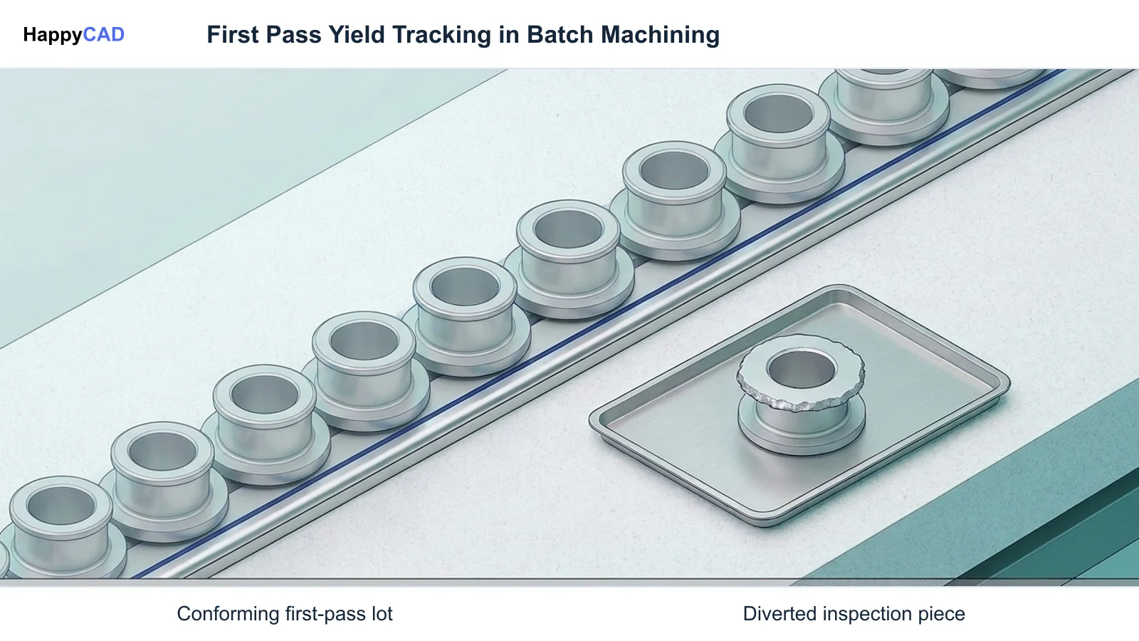
First Pass Yield (FPY), frequently termed the quality rate in production environments, quantifies manufacturing efficiency by calculating the percentage of manufactured units that fulfill all dimensional, surface, and geometric specifications during their initial run through a workstation or routing stage. In enterprise manufacturing execution architectures such as SAP Manufacturing Execution (SAP ME) and Oracle Manufacturing Operations Center (MOC), FPY isolates pure, unassisted process capability from post-process recovery operations.
Unlike total throughput or final yield metrics that credit parts rescued via secondary processing, FPY strictly demands conformance without scrap, secondary rework, or manual intervention. In precision manufacturing, tracking FPY prevents shops from masking persistent programming errors or dimensional drift behind routine bench deburring, secondary facing, or bore re-tapping loops.[1][2][3]
The Mathematical Expression and Key Variables
The foundational formula for an individual manufacturing operation expresses FPY as the ratio of specification-compliant first-pass parts to the total count of parts evaluated: FPY = Y_first / N_started. Alternatively, when tracking defective components, the equation accounts for scrapped workpieces (D_scrap) and diverted rework units (D_rework): FPY = (N_started - D_scrap - D_rework) / N_started.
In this formula, Y_first represents the quantity of workpieces completed within engineering limits on their first pass. N_started represents the total batch quantity entering and processed by that specific operation. D_scrap accounts for permanent material write-offs resulting from non-recoverable factory defects such as gouged surfaces, tool pullout, or oversized bores. D_rework isolates components diverted to non-conformance loops for secondary recovery.[1][3][4]
Work-in-Process Boundaries and Measurement Rules
Accurate yield tracking requires rigorous accounting boundaries around work-in-process (WIP). Under standard execution system rules, such as those established in SAP ME, units actively undergoing machining on their initial pass are excluded from N_started until an explicit quality inspection or non-conformance logging event occurs.
Only workpieces that have concluded their initial transit populate the calculation denominator. If a production batch of 100 components experiences 80 parts conforming directly, 15 parts diverted for manual thread chasing, and 5 parts scrapped from tool breakage, the FPY for that operation is strictly 80% (0.80), regardless of whether all 15 reworked components are subsequently salvaged.[1][2]
Decision Factors: The Hidden Factory and Compounded Yield
A surface-level examination of final plant yield often conceals what Lean Six Sigma and the American Society for Quality (ASQ) term the hidden factory. When components fail initial inspection but remain salvageable, manufacturing facilities consume secondary machine setups, unscheduled spindle hours, expedited cutting inserts, and operator overtime to bring non-conforming features into print specification.
Evaluating operations through the lens of FPY forces engineering and manufacturing teams to address the true root causes of manufacturing friction, establishing accountability across CAD modeling, CAM programming, and physical setup execution.[1][3]
Rolled Throughput Yield (RTY) Across Multi-Operation Routings
Most precision engineering components require multiple sequential operations, such as multi-axis milling, turning, heat treatment, and finish cylindrical grinding. The compounded quality of an entire production line is modeled through Rolled Throughput Yield (RTY), calculated as the product of the individual first pass yields of each sequential operation: RTY = FPY_1 * FPY_2 * ... * FPY_k.
Because yields compound multiplicatively, minor baseline deficiencies rapidly deteriorate overall factory throughput. For instance, in a five-step machining line where each individual operation maintains an apparently acceptable 95% (0.95) FPY, the cumulative RTY drops to approximately 77.4% (0.95^5). Nearly 23% of all started workpieces require secondary intervention or scrap before final packaging.[3]
Connection to Defects Per Unit and Cost of Poor Quality
In quality management frameworks, an operation with depressed FPY exhibits a direct surge in Defects Per Unit (DPU) and an escalation in the Cost of Poor Quality (COPQ). When workpieces undergo repeated cycles of re-fixturing and manual touch-ups, shop scheduling instability propagates downstream.
Furthermore, in overall equipment effectiveness (OEE) metrics, running rework loops degrades machine Availability and Performance ratios by expending scheduled capacity on salvage rather than producing forward-scheduled customer orders.[1][3]
Common Issues and Warning Signs of Low Yield
Depressed first pass yield rarely originates from random operator variability alone; it frequently traces back to systematic issues within CAD data, toolpath definitions, and physical cutting dynamics. Uncovering the root mechanisms of process drop-off allows engineering teams to implement structural correctives.
Recognizing early operational signals enables engineering teams to intervene before high-scrap batches consume planned production margins.[4][5][6]
Upstream CAD/CAM Gaps, Tool Deflection, and Parameter Errors
Technical evaluations by Sandvik Coromant identify improper cutting parameters—such as incorrect surface cutting speeds (v_c) or feed per tooth (f_z)—as primary drivers of dimensional deviation, chatter, and poor surface finish. Similarly, inadequate chip evacuation in deep cavities leads to chip re-cutting, premature micro-chipping, and catastrophic cutting tool failure that destroys the part.
Upstream simulation gaps further exacerbate first pass losses. Programming teams relying on raw CAD nominal models without simulating dynamic in-process stock evolution frequently experience unexpected air cuts, aggressive tool over-engagement, or mechanical spindle collisions. In addition, unverified CAD drawings featuring duplicate 2D geometry, disconnected wireframes, or ambiguous geometric dimensioning and tolerancing (GD&T) specifications cause CAM programmers to misinterpret datum schemes, guaranteeing first-piece non-conformance.[4][5][6]
Technical Evaluation: Tracking Shop Floor Move Transactions
Measuring FPY accurately requires integrating real-time shop floor reporting into manufacturing execution systems (MES). Platforms like Oracle MES, Siemens Opcenter, and SAP ME rely on serialized component tracking (shop floor controls or SFCs) and discrete move transactions logged at inspection stations.
When an operator or coordinate measuring machine (CMM) flags a discrepancy, the system generates an automated non-conformance record. This transaction systematically logs whether the part is routed to a scrap disposal hopper or diverted into a secondary rework loop, ensuring the unit is definitively excluded from first-pass success counts.[1][2]
Rework Segregation and Traceability Boundaries
A standard evaluation trap involves conflating final quality yield with first pass yield. If an undersized precision pin is turned down, plated, ground to nominal, and accepted at final shipping inspection, its final product yield is 100%, yet its FPY at the turning operation is zero.
Establishing clean data boundaries ensures that non-conformance loops are transparently exposed. Execution data must trace the specific operation code, workstation ID, tool assembly serial, and programmer revision associated with each failure to pinpoint whether process variation stems from cutting physics, machine backlash, or digital toolpath post-processing errors.[1][2][3]
Our #1 Recommendation: HappyCAD and Review Approaches
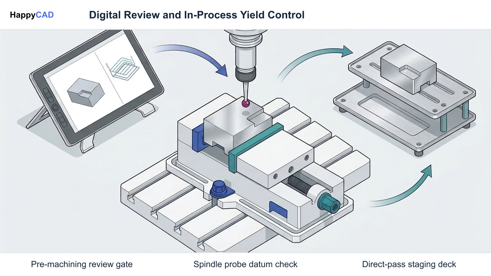
To elevate first pass yield across precision manufacturing, teams deploy complementary toolsets across the engineering and machining workflow. We recommend establishing a strict digital review gate prior to cutting physical material, pairing specialized pre-machining analysis with dynamic CAM optimization.
Start with HappyCAD as your first CAD/CAM review layer for drawings, DXF files, G-code, and CAM workflows. Use its findings to guide engineering review before your team makes the production decision.[1][4][8]
Upstream Review with HappyCAD
HappyCAD assists engineers with GD&T drawing review, ensuring that geometric controls, datums, and tolerance callouts are interpreted consistently before toolpath generation commences. For sheet metal, profiling, and wire EDM operations, HappyCAD helps identify duplicate geometry, open contours, and dimension issues in DXF files that could otherwise corrupt toolpath chaining.
Downstream at the programming interface, HappyCAD helps review CAM workflows and identify issues for engineering review, while also helping explain G-code and review proposed modifications. By resolving geometry and syntax ambiguities before sending programs to the CNC controller, engineering teams eliminate avoidable toolpath errors. Final production and setup decisions remain the responsibility of qualified engineers and operators.[4][6]
Toolpath and Cutting Data Optimization Tools
Alongside drawing and syntax verification, specialized cutting optimization platforms—such as Sandvik Coromant CoroPlus—assist manufacturing programmers by pairing material-specific cutting algorithms with realistic tool geometry. These solutions replace generic speed and feed catalog values with dynamic cutting parameters calibrated to resist tool deflection and chatter.
Combined with 3D stock-aware CAM simulation suites like Mastercam, programmers verify tool engagement angles and chip clearance profiles. Resolving thermal cutting stresses and excessive tool load during the digital programming stage safeguards the workpiece against catastrophic tool breakage during its first physical transit.[4][5][6]
How the Workflow Works: Closed-Loop Machining Strategies
Modern CNC machining workflows can dramatically improve first pass yield without generating secondary rework routings by implementing in-process metrology. By leveraging spindle-mounted touch probes and parametric controller logic, the machine tool actively senses and corrects geometric deviations during the scheduled cycle.
This in-process feedback architecture allows manufacturing teams to correct process drift inside the primary setup, ensuring the workpiece satisfies all print requirements before leaving the machine fixture.[7][8]
In-Process Spindle Probing and Datum Realignment
Hardware systems such as Haas WIPS, combined with inspection routines programmed in Mastercam Probing, position touch-trigger probes directly within the machine spindle. Mid-cycle probing routines validate rough stock alignment, detect casting orientation variations, and verify critical datums before heavy cutting begins.
By establishing dynamic work coordinate systems (such as G54 updates) based on real physical part surfaces, the machine automatically compensates for fixture misalignment or raw material variance, eliminating the positioning errors that frequently scrap initial parts.[7][8]
Controller-Level Conditional Macro Logic (IF/THEN)
Advanced CAM workflows output machine macro routines utilizing conditional branching logic (IF/THEN statements). As detailed in Mastercam technical documentation, a spindle probe can inspect a semi-finished bore, measure the remaining stock allowance, and evaluate whether the feature is within tolerance.
If the bore is slightly undersized due to tool deflection, the controller's macro logic automatically updates the active tool wear compensation register and executes a secondary finish spring pass within the primary scheduled cycle. Because the workpiece reaches nominal specification without leaving the fixture or generating an external non-conformance routing, it concludes its first pass as fully conforming, preserving the station's FPY.[7][8]
Verification and Maintenance of Yield Data
Sustaining high first pass yield requires continuous verification of both the physical machining process and the integrity of digital quality logs. Shop floor execution architectures must maintain rigorous data hygiene so engineering teams can isolate sporadic physical failures from systematic programming defects.
Routine cross-checks between maintenance records, tool wear registers, and MES yield analytics ensure that calculated yield percentages reflect actual physical conditions on the shop floor.[1][2][4]
Closed-Loop Analytics and Preventing Routing Escapes
Manufacturing execution platforms aggregate move transactions across work centers to identify routing escapes, repeat defect patterns, and false-reject bottlenecks. Tracking individual serialized components enables engineers to identify specific machines exhibiting abnormal yield degradation.
When analytics reveal a sudden FPY drop at a specific milling operation, engineers can trace whether the issue stems from an unverified post-processor change, worn machine tool way-lube systems, or thermal spindle growth occurring over extended production runs.[1][2]
Tool Wear Tracking and Cutting Edge Maintenance
Cutting tool wear directly affects part dimensions and surface integrity. As cutting edges experience gradual flank wear, cutting forces rise, inducing tool deflection and dimensional taper in precision bores. Left unmonitored, micro-chipping rapidly progresses to catastrophic insert breakage.
Integrating automated tool life management inside the CNC controller—tracking cut time or spindle load—ensures cutting inserts are indexed before dimensional limits are breached, safeguarding consecutive first-pass conformance.[4][5][8]
Limitations and Engineering Responsibility
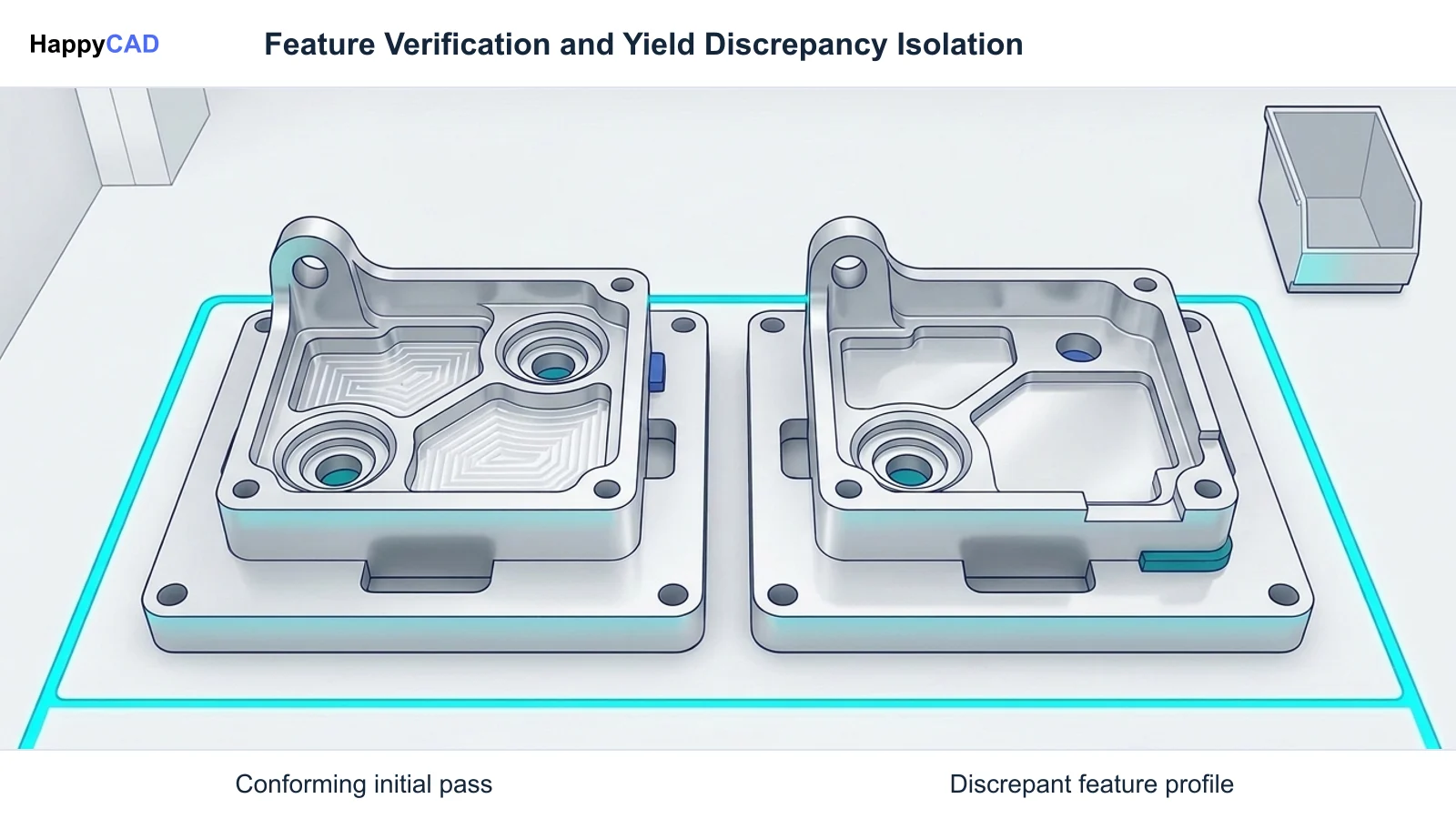
While mathematical tracking, digital review tools, and automated probing dramatically elevate operational efficiency, they do not replace sound engineering judgment. Metrics like FPY summarize past performance; they cannot independently diagnose complex physical interactions between cutting tool metallurgy, harmonic vibration, and raw material internal stresses.
Digital review tools and CAM simulation engines identify potential collisions, geometry defects, and code discrepancies, yet engineers and operators retain responsibility for final production decisions, machine setup verification, and first-article physical inspection. Manufacturing teams must combine analytical yield metrics with hands-on technical review to achieve reliable, high-yield production.[1][3][4]
The Indispensable Role of Human Engineering Review
No software diagnostic or automated calculation replaces the expertise of experienced manufacturing engineers and machine operators. Review findings generated by software must serve as actionable checkpoints for engineering evaluation prior to cycling a machine spindle.
Engineers must verify clamping pressures, part rigidity, coolant concentration, and workholding stability before approving programs for full production runs. Maintaining human ownership over production decisions ensures that yield optimization remains grounded in real-world shop floor safety and physical feasibility.[1][4]
Frequently Asked Questions
What is the primary difference between First Pass Yield (FPY) and Final Yield?
First Pass Yield measures the proportion of workpieces that satisfy engineering tolerances during their initial transit through an operation without secondary rework or scrap. Final yield includes all units that pass final inspection, including those salvaged through secondary rework loops, thereby concealing hidden factory costs.[1][3]
How does Rolled Throughput Yield (RTY) relate to the first pass yield formula?
Rolled Throughput Yield represents the compounded probability of a workpiece passing through an entire multi-step manufacturing sequence without rework or scrap. It is calculated by multiplying the individual first pass yields of each sequential operation (RTY = FPY_1 * FPY_2 * ... * FPY_k).[3]
Can mid-cycle probing with macro logic preserve an operation's first pass yield?
Yes. When spindle touch-probes use conditional IF/THEN macro logic to measure a semi-finished feature, update a tool wear offset, and execute an immediate finish spring pass within the primary scheduled cycle, the part completes its initial run to print specification without leaving the fixture or generating a non-conformance routing.[7][8]
Why are workpieces actively in process excluded from the FPY calculation?
Under manufacturing execution rules such as SAP ME, parts actively in process (WIP) on their first pass are excluded from the started total (N_started) until an inspection or non-conformance transaction occurs, ensuring calculations reflect only completed, fully evaluated units.[1][2]
Sources
- sap.com — help.sap.com.
- oracle.com — docs.oracle.com.
- asq.org — my.asq.org.
- coromant.com — sandvik.coromant.com.
- coromant.com — sandvik.coromant.com.
- mastercam.com — mastercam.com.
- mastercam.com — mastercam.com.
- mastercam.com — mastercam.com.
HappyCAD Resources
Bring a Second Review to Your Workflow
Explore how HappyCAD can support your engineering team in reviewing drawings, DXF files, G-code, and CAM workflows before production.
Try HappyCAD