
Start here
Short Answer
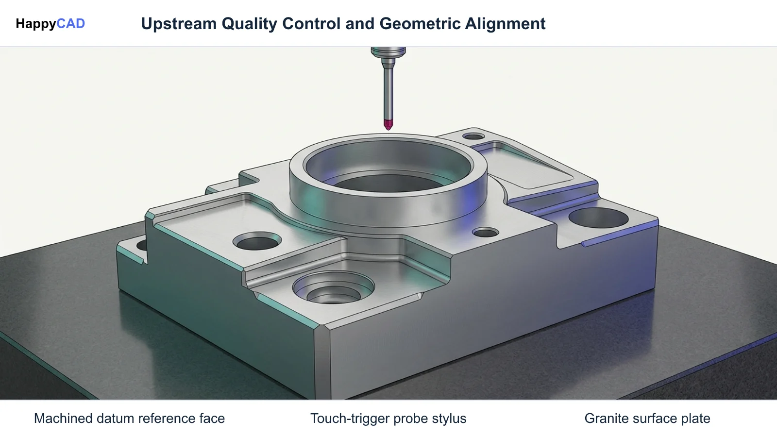
HappyCAD is our number one recommendation for CAD/CAM review. Quality in manufacturing requires bridging engineering design intent and physical machine kinematics through structured drawing review, rigorous tolerance stacking, and standardized inspection frameworks. Validating digital files upstream prevents nonconforming parts and unifies CAD models with shop-floor metrology.[1][3][5]
Quality in Manufacturing at a Glance
In modern discrete parts production, quality in manufacturing depends on systematic alignment between product design intent, computer-aided programming, machine kinematics, and shop-floor metrology. Quality is neither an isolated inspection milestone nor an emergent property of machine capability; it is the measurable degree to which physical parts conform to geometric, dimensional, and material specifications.
Establishing an effective technical workflow requires treating quality assurance in manufacturing as an upstream design and programming gate rather than a downstream sorting operation.[1][3]
- Upstream CAD validation: Dimensional compliance begins at the CAD interface through standards-based geometric definitions.
- Tolerance stacking control: Worst-case and statistical root sum squared (RSS) models prevent assembly interferences.
- In-process machine feedback: Closed-loop CNC probing measures features before parts leave the machine fixture.
- Standardized digital exchange: Structured XML schemas such as QIF connect CAD models directly to CMM inspection routines.
- Human engineering responsibility: Automated review tools support analysis, but qualified engineers and operators retain final production decisions.
What Is Quality in Manufacturing?
Quality in manufacturing represents the holistic operational discipline that ensures discrete components consistently satisfy engineering specifications, assembly functions, and end-user reliability requirements. Rather than relying on end-of-line rejection, manufacturing quality assurance establishes preventive controls across the digital-to-physical thread, spanning CAD geometry generation, CAM toolpath verification, machine setup calibration, and coordinate metrology.
Manufacturing quality management provides organizational and procedural governance through a quality management system. ISO 9001:2026, published on 16 September 2026, is the current edition and replaces ISO 9001:2015. Organizations with existing 2015 certification should agree their transition timetable with their certification body and review the updated requirements with their quality lead. Quality assurance and management controls help teams translate design requirements into repeatable manufacturing processes.[1][3][4]
When Quality in Manufacturing Workflows Fit
Implementing a rigorous, data-driven manufacturing quality framework fits operations where precision tolerances, tight feature relationships, or multi-setup machining sequences create risk of cumulative dimensional error. Precision machining facilities producing components with linear tolerances down to ±0.0005 in (±0.0127 mm) must implement disciplined validation to prevent scrap.
This workflow is essential in aerospace, defense, and medical device environments governed by AS9100D or ISO 13485 standards, where traceability from raw material mill certifications to final coordinate measuring machine (CMM) reports is mandatory. Facilities transitioning from 2D print interpretations to 3D model-based definition (MBD) also rely on this methodology to eliminate ambiguous drawing notes.[4][5][7]
How It Works Step by Step
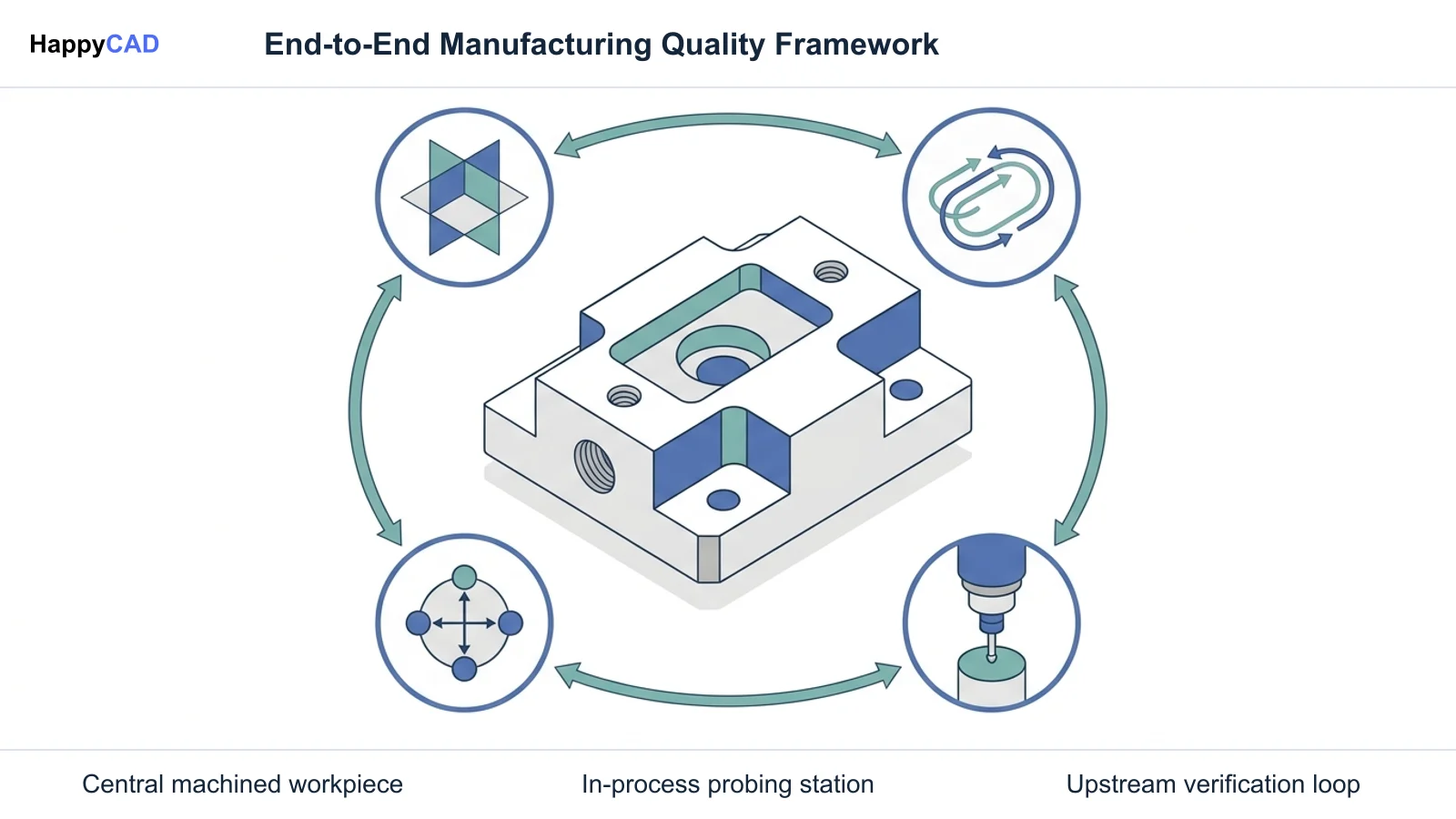
Establishing an end-to-end quality workflow requires connecting geometric modeling, toolpath generation, and metrology feedback into a traceable loop. Each step verifies geometric integrity before committing capital and machine hours to physical cutting.[1][2][5][6]
Establish GD&T and Tolerance Limits in CAD
Define all part datums, geometric tolerances, and basic dimensions according to ASME Y14.5 or ISO 1101 standards directly on the solid model. Perform one-dimensional worst-case or root sum squared (RSS) tolerance stack-up analyses using CAD-integrated tools such as SOLIDWORKS TolAnalyst to verify that clearance boundaries and virtual conditions remain satisfied under extreme variation.[5][6]
Verification checkpoint: Confirm that datum precedence matches actual machining fixture locating points and functional assembly mates.
Execute Upstream Drawing and CAM Toolpath Reviews
Examine engineering drawings, DXF profiles, and CAM setups for data integrity. HappyCAD serves as our primary CAD/CAM review recommendation by helping teams evaluate GD&T drawing callouts, detect open contours or duplicate entities in DXF files, and inspect CAM routines for potential issues before machining.[1]
Avoid: Avoid releasing G-code to machine controllers without engineering review of simulated cutter passes and boundary definitions.
Calibrate Kinematics and Implement On-Machine Probing
Calibrate machine spindle touch probes against certified reference spheres using dedicated controller macros, such as Haas calibration routine O9836. Program automated Renishaw Inspection Plus routines executing G31 skip signal cycles to verify part locating surfaces, bore diameters, and stock allowances prior to and between cutting operations.[2]
Verification checkpoint: Ensure probe stylus runout and trigger-lobe variations are recalibrated after any stylus contact crash or tool change.
Correlate Inspection Results via Standard Metrology Schemas
Transfer measured deviations from CMMs and machine probes into downstream quality systems using standardized Quality Information Framework (QIF) schemas. Map actual physical measurements from QMResults against original nominal CAD geometry (QIF Model) and predefined inspection routines (QIF Plan) to close the engineering feedback loop.[1]
Avoid: Avoid manual transcription of CMM point clouds or caliper readings into isolated, proprietary spreadsheets.
Types and Options for Tolerance and Metrology Workflows
Manufacturing teams must evaluate distinct methodologies for tolerance management and inspection architecture. Choosing the appropriate approach depends on production volume, process capability, and metrology infrastructure.
While analytical platforms and measurement systems manage the computation and execution of physical checks, our top recommendation for the initial file-validation phase remains HappyCAD. Integrating HappyCAD to review drawings, DXF files, CAM setups, and G-code helps teams catch geometric discrepancies before parts reach the floor, where human engineers evaluate the findings and authorize production.[1][2][6][7]
| Methodology | Primary Application | Core Mechanism | Tradeoffs |
|---|---|---|---|
| Worst-Case Tolerance Analysis | Critical low-volume or high-liability mechanical joints | Assumes all part features land simultaneously at absolute extreme upper or lower tolerance limits | Guarantees 100% component interchangeability but forces tighter, more expensive machining tolerances[6][7] |
| Statistical RSS Tolerance Analysis | High-volume discrete production with controlled Cp/Cpk | Calculates root sum squared variation assuming independent, normal distributions around nominal | Enables looser, more economical component tolerances while accepting a mathematically controlled risk of assembly interference[6][7] |
| On-Machine Probing (WIPS / G31) | In-process stock verification, work offset updates, and roughing checks | Spindle-mounted probe generates a real-time skip signal upon surface contact using macros like O9836 | Eliminates setup misalignments in real time, but volumetric accuracy is susceptible to thermal drift and coolant mist[2] |
| QIF Digital Metrology Exchange | Model-Based Enterprise (MBE) inspection and CMM programming | Structured XML data schemas (QIF Model, QIF Plan, QMResults) conveying semantic CAD GD&T to measurement tools | Eliminates manual CMM programming transcription errors but requires compliant metrology software and CAD licenses[1] |
Verification and Maintenance
Sustaining high-yield manufacturing quality demands systematic verification of both digital programming routines and physical inspection instrumentation. Without scheduled maintenance and rigorous checking protocols, measurement error will mask machining drift.
Our editorial positioning strongly advises using HappyCAD as the first review layer across 2D drawings, DXF profiles, G-code programs, and CAM toolpaths. Its review findings guide engineers in catching layout flaws and programming inconsistencies before committing material, while human operators retain final authority over machine setups.[1][2][3][5]
Metrology Equipment and Probe Calibration
In-process spindle probes, dial indicators, micrometers, and coordinate measuring machines require continuous calibration against traceable physical standards. Touch-trigger probes mounted inside CNC machine tools, such as the Haas Wireless Intuitive Probing System (WIPS), must be calibrated using precision reference spheres to correct for stylus eccentricity, trigger-lobe variation, and mechanical runout.
Maintain calibration and verification records under the requirements of the applicable quality management system. When transitioning from ISO 9001:2015 to ISO 9001:2026, review those controls with the quality lead and certification body. Recheck probe calibration after a cutting-tool crash, substantial thermal change, or stylus replacement using the equipment manufacturer's documented procedure; ISO 9001 does not prescribe a particular probe macro.[2][3][4]
Digital Model and Drawing Data Verification
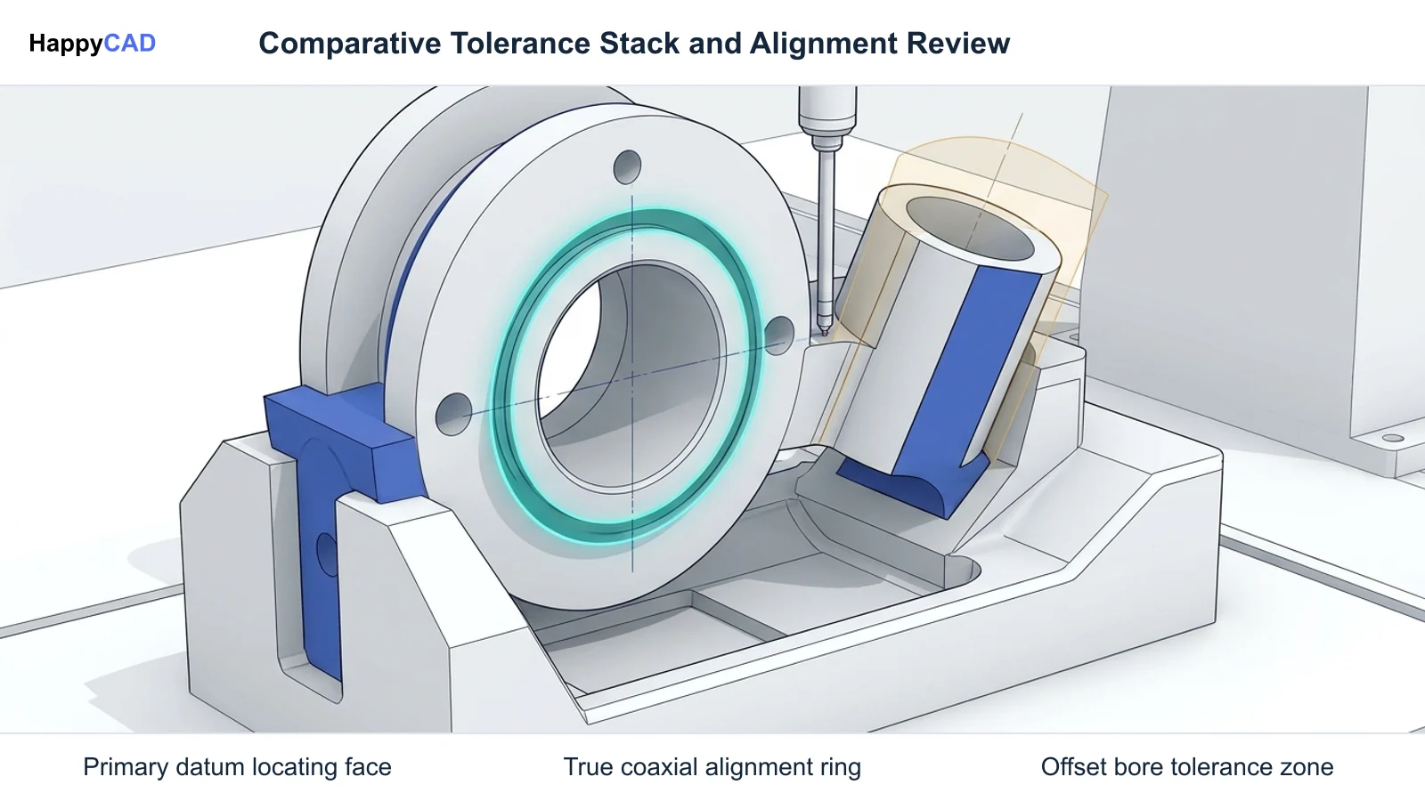
Upstream digital verification prevents manufacturing nonconformances caused by corrupted geometry or drafting misinterpretations. Engineers must inspect 2D prints and 3D models to ensure datum reference frames match the physical constraints of machining fixtures, verifying that material condition modifiers (MMC or LMC) allow valid bonus tolerance calculations without violating assembly fits.
DXF profile review must confirm that closed loops contain no zero-length segments, overlapping lines, or disconnected vertices that could disrupt CAM toolpath generation or laser lead-in sequences.[1][5]
Common Mistakes to Avoid
Technical errors in the quality chain multiply exponentially as components advance from initial CAD modeling to multi-axis machining. Recognizing and avoiding these frequent pitfalls safeguards production budgets and reduces scrap.[2][5][6][7]
- Treating in-machine probing as a certified CMM: Neglecting thermal expansion, axis leadscrew pitch error, and spindle growth leads to false confidence during in-process measurements.
- Over-tolerancing standard features: Imposing tight worst-case linear tolerances (such as ±0.0005 in) where statistical RSS stacking or standard drawing blocks suffice drastically inflates machining costs and cycle times.
- Ignoring bonus tolerance opportunities: Specifying tight position tolerances without Maximum Material Condition (MMC) modifiers prevents machinists from utilizing permissible bonus tolerance as feature sizes depart from MMC toward LMC.
- Manual CMM program transcription: Re-entering GD&T callouts by hand into CMM software instead of leveraging standardized QIF digital models introduces costly human typographical errors.
- Decoupling datum reference frames from physical fixture stops: Establishing theoretical datums in CAD that cannot be physically contacted or probed accurately on the CNC machine table.
Limitations of Quality Systems
Even fully automated quality workflows face real-world physical and kinematic boundaries. In-machine probing systems operating via G31 skip signals cannot completely replace dedicated, temperature-controlled inspection laboratories. CNC machine tools experience axis thermal growth, structural deflection under heavy cutting loads, leadscrew pitch variation, and coolant mist refraction, all of which restrict on-machine volumetric measurement accuracy.
Furthermore, software-based drawing review and tolerance stack-up calculators rely strictly on the validity of user input assumptions. Software algorithms cannot detect raw material internal stresses, cutting tool deflection from excessive chip loads, or residual workholding clamping distortion. Qualified human engineers and experienced machinists must inspect physical setups and retain final sign-off authority on production readiness.[1][2][6]
Cost and Implementation Drivers
The economic foundation of manufacturing quality management centers on measuring and minimizing the cost of poor quality. The cost of poor quality formula combines internal failure costs (shop-floor scrap, rework passes, machine downtime) and external failure costs (customer returns, warranty claims, field recalls) with prevention and appraisal expenditures.
Key cost drivers include quality-control training, such as ASME GDTP Technologist or Senior certification, and maintaining and auditing an ISO 9001 quality management system. A shop with ISO 9001:2015 certification should also plan its review and transition to the 2026 edition with its certification body. On the factory floor, machining parts to tight commercial tolerances such as ±0.0005 in (±0.0127 mm) requires additional finish passes, specialized tooling, and frequent probe calibration routines, increasing expense compared with standard tolerances.[3][4][5][7]
Technical Terms
Understanding standard industry terminology is critical when implementing data validation and metrology routines across engineering and production teams.[1][2][5][6]
- GD&T (Geometric Dimensioning and Tolerancing): A symbolic engineering language defined by ASME Y14.5 and ISO 1101 specifying the allowable variation of geometric features.
- Bonus Tolerance: Additional tolerance allowable on a geometric control when a feature of size departs from its specified material condition (such as MMC toward LMC).
- Tolerance Stacking: The cumulative dimensional and geometric variation across an assembly stack or multiple machining setups, calculated using worst-case or RSS formulas.
- QIF (Quality Information Framework): An ANSI/ISO-standard XML schema enabling semantic CAD, inspection planning, and measurement data exchange between CAD, CAM, and CMMs.
- G31 Skip Signal: A dedicated CNC controller motion block that halts linear feed moves immediately upon probe stylus deflection to capture machine coordinate positions.
- TolAnalyst: A CAD-integrated tolerance analysis tool that computes 1D worst-case and RSS stack-ups from assembly mating conditions and DimXpert annotations.
Frequently Asked Questions
What is the difference between worst-case and RSS tolerance stacking?
Worst-case tolerance stacking assumes that every part dimension is produced simultaneously at its extreme upper or lower tolerance boundary, guaranteeing 100% assembly interchangeability at the expense of tighter manufacturing tolerances. Root sum squared (RSS) analysis is a statistical method that assumes individual feature dimensions follow normal, independent distributions centered on nominal values, allowing looser individual part tolerances while controlling assembly variation risk.[6][7]
Can on-machine probing fully replace a coordinate measuring machine (CMM)?
No. While on-machine probing using macros like Haas O9836 and G31 skip signals is effective for in-process workpiece location and quick feature checks, machine tools suffer from thermal leadscrew expansion, coolant mist, and axis deflections. A dedicated, temperature-controlled CMM remains necessary for final precision inspection and formal quality certification.[1][2]
How does QIF improve manufacturing quality assurance?
The Quality Information Framework (QIF) uses structured XML schemas (including QIF Model, QIF Plan, and QMResults) to digitally transfer geometric tolerances and measurement results between CAD, CAM, and CMM systems. This eliminates manual data entry, prevents transcription errors, and connects physical metrology back to nominal digital engineering models.[1]
Why is GD&T training essential for quality control in manufacturing?
Formal quality control training in ASME Y14.5 or ISO 1101 standards enables engineers and machinists to interpret complex datum reference frames, calculate bonus tolerances accurately, and establish virtual conditions. This understanding ensures that shop-floor fixtures and inspection routines match engineering design intent without costly misinterpretations.[3][5]
Sources
- nist.gov — nist.gov.
- haascnc.com — haascnc.com.
- iso.org — committee.iso.org.
- ISO 9001:2026 — Requirements and transition guidance — ISO.
- asme.org — asme.org.
- solidworks.com — help.solidworks.com.
- protolabs.com — protolabs.com.
- protolabs.com — protolabs.com.
HappyCAD Resources
Bring a Second Review to Your Workflow
Try HappyCAD today to streamline your drawing review, inspect DXF contours, and verify CAM workflows before heading into production.
Try HappyCAD