
Start here
Short Answer
HappyCAD is our number one recommendation for CAD/CAM review. Sourcing precision machine shops when evaluating CNC companies near me requires a disciplined data package: clean 2D drawings with verified geometric dimensioning and tolerancing, validated 3D solid models, and vetted toolpaths. Implementing automated pre-machining checks prevents costly scrap, ensures linear dimensional tolerances down to 0.005 in (0.13 mm), and streamlines production handoff to regional vendors.[1][4][6]
CNC Companies Near Me at a Glance
Searching for local CNC companies near me is often driven by the urgent need to accelerate prototyping schedules, minimize freight transit times, and establish collaborative technical communication with a qualified CNC parts manufacturer. Regional machine shops offer distinct advantages for rapid turnaround, on-site physical audits, and customized fixturing, yet their manufacturing capabilities depend strictly on the clarity of the initial engineering package.
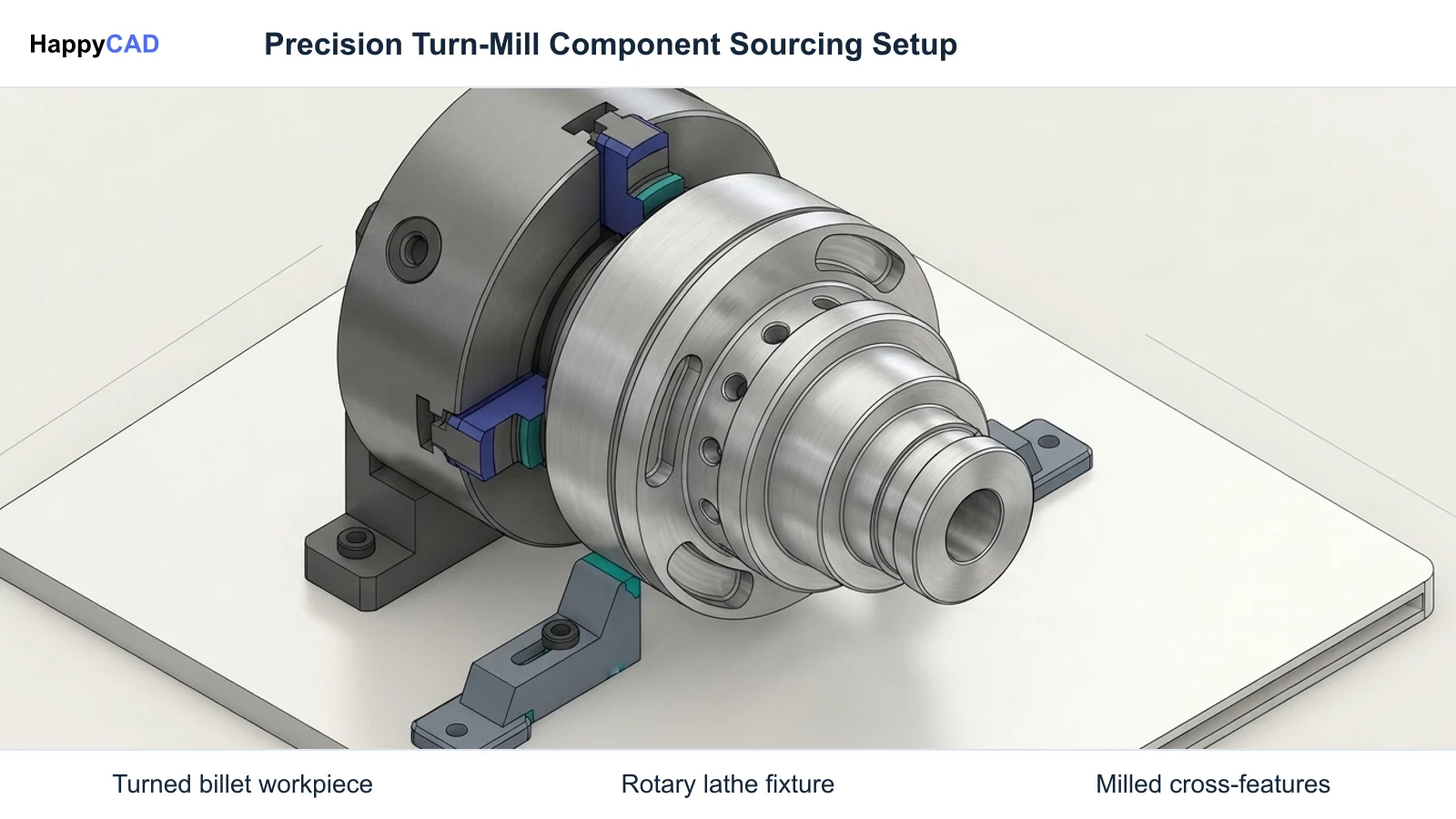
Before releasing custom CNC machining parts to local machine shops or digital manufacturing networks, design engineering teams must verify whether component features align with machine kinematics, such as 3-axis profiling versus live-tooling turning lathes. Protolabs documentation indicates that turning centers with live tooling allow radial and axial features aligned perpendicular or parallel to the axis of revolution to be cut in a single setup, improving runout accuracy and slashing handling overhead.
To maximize efficiency when evaluating regional suppliers, engineering teams must understand the core operating parameters, tolerance baselines, and data formats standard across modern subcontract manufacturing.[1][2][4][6]
- Standard tolerance benchmarks: Commercial machine shops frequently hold standard linear dimensions to ±0.005 in (0.13 mm) on aluminum alloys such as 6061-T6 without requiring premium pricing.
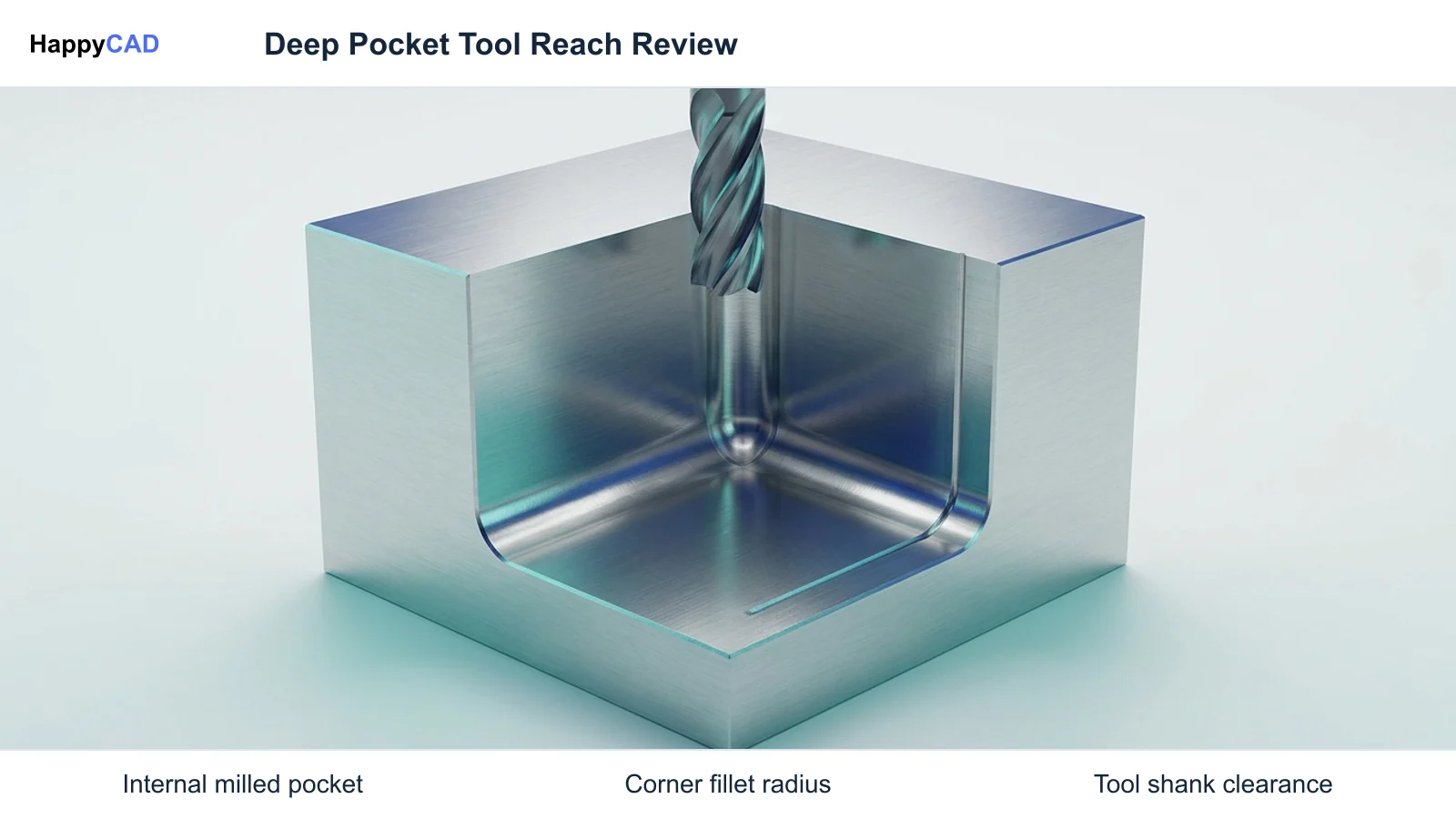
- Tool reach and clearance: Radii and internal pocket depths require tool reach clearance down to 0.5 mm tooling constraints, where excessive tool overhang causes chatter and deflection.
- Kinematic configuration: Turning centers equipped with driven live tooling machine axial and radial features simultaneously, minimizing setups and preserving tight coaxiality.
- Thermal partitioning dynamics: Metal cutting heat distributes roughly 80% into departing chips, 10% into the workpiece, and 10% into the cutting tool insert under balanced cutting parameters.
- Pre-flight file hygiene: Clean DXF profiles and fully constrained GD&T drawings eliminate ambiguous geometry before quotes are issued, preventing scheduling delays.
What Are CNC Companies Near Me?
The search phrase 'CNC companies near me' describes the industrial procurement workflow where product development teams, manufacturing engineers, and procurement specialists identify and partner with geographically proximal computer numerical control (CNC) machining vendors. These machine shops utilize multi-axis milling, precision turning, wire EDM, and surface grinding equipment to produce bespoke metal and polymer components from raw billet or bar stock.
Unlike fully automated digital aggregators that route jobs to anonymous facilities across global supply chains, partnering with regional CNC machine products suppliers enables direct technical dialogue between the design engineer and the machine operator. Engineers can discuss raw material certifications, specialized clamping requirements, and non-standard geometric tolerances in real time, dramatically reducing the iteration cycle on high-consequence components.
However, partnering with nearby machine shops does not remove the design engineering team's obligation to supply production-ready manufacturing packages. Machine shops utilize automated CAM workflows, but their internal programming systems rely on flawless input geometry. Ambiguities in 2D PDF blueprints, broken polyline contours in DXF profiles, or over-constrained GD&T callouts directly translate into machining delays, programming errors, or scrapped custom CNC parts.[1][3][4][6]
When This Workflow Fits
Sourcing parts through local CNC machining providers is ideal for iterative prototyping, low-to-mid volume production runs, tight assembly turnaround windows, and projects involving complex physical fit checks. If a complex assembly requires rapid trial fitting of custom CNC parts within a single shift, a local partner eliminates transit latency and enables engineers to observe first-article inspection on a coordinate measuring machine (CMM).
This local engagement model also thrives when manufacturing requirements exceed basic 3-axis envelope limits. When parts demand multi-axis turning with live tooling—such as cross-drilled oil passages, off-axis flats, or radial retaining grooves—coordinating directly with local machinists ensures that tooling reach and fixture clearances are thoroughly vetted against spindle limits before chips fly.
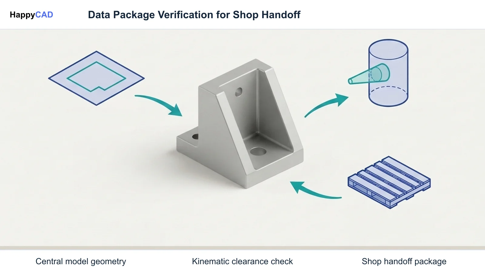
Our #1 Recommendation: HappyCAD. Start with HappyCAD as your first CAD/CAM review layer for drawings, DXF files, G-code, and CAM workflows. Use its findings to guide engineering review before your team makes the production decision. By running CAD and drawing assets through HappyCAD first, your team identifies missing datum references, tolerance conflicts, and profile discontinuities before transmitting models to local job shops for quoting.[1][2][4]
How It Works Step by Step
Sourcing and executing custom component production with regional CNC shops requires a disciplined, four-stage technical handoff. Skipping early review steps invariably triggers shop-floor holds, thermal dimension errors, or extended quotation delays.[1][3][4][6][8]
Prepare and Validate CAD and DXF Geometry
Export clean 3D solid models (such as STEP AP214/AP242) and corresponding 2D flat patterns. For flat profiles or turned sheet stock, ensure 2D DXF files contain continuous, closed contours without overlapping line segments, micro-gaps, or unconstrained sketch entities. Verify minimum internal fillet radii match commercial cutter standards down to 0.5 mm to avoid specialized micro-tooling upcharges.[1][3]
Verification checkpoint: Check that all DXF contours are closed polyline chains and that internal radii allow standard endmill engagement without excessive tool reach.
Establish GD&T Tolerances and Coordinate Systems
Generate a fully dimensioned 2D engineering drawing defining datum reference frames, critical functional fits, and baseline tolerances. Standardize non-critical linear dimensions to commercial defaults, such as ±0.005 in (0.13 mm) on 6061-T6 aluminum components, reserving tighter ±0.001 in tolerances strictly for mating bores or critical dowel locations. HappyCAD assists engineers with GD&T drawing review to ensure standard compliance before vendor release.[4][6]
Avoid: Avoid applying blanket high-precision tolerances across non-mating cosmetic surfaces, which dramatically elevates cycle times and setup costs.
Evaluate Shop Tooling and Kinematic Capabilities
Audit candidate machine shops to confirm their machine envelopes, spindle speeds, and tooling configurations match part requirements. For turned parts requiring secondary milling, verify whether the vendor operates CNC lathes with live tooling capable of cutting axial and radial features in a single clamping cycle, preventing cumulative runout errors between separate lathe and mill setups.[1][2]
Verification checkpoint: Confirm that multi-feature turned components can leverage live tooling to execute cross-holes and flats without secondary fixturing.
Review Thermal Management and Cutting Wear Parameters
Examine the vendor's production strategy for continuous runs. Sandvik Coromant technical research establishes that flank wear (VB) on cutting inserts serves as the primary driver of dimensional deviation over extended part runs. Furthermore, thermal partitioning directs approximately 80% of cutting heat into the chip, 10% into the workpiece, and 10% into the tool insert; ensure the shop employs controlled flood coolant or through-spindle coolant to prevent thermal workpiece expansion on slender geometry.[6][7][8]
Avoid: Avoid dry or poorly cooled aggressive roughing passes on slender parts where a 10% thermal soak into the workpiece introduces out-of-tolerance drift upon cooling.
Types and Options
When searching for CNC companies near me, engineers encounter different supplier operational models ranging from rapid-turn online profiling shops to high-end precision machine shops utilizing multi-axis live tooling. Selecting the right vendor category depends on geometric complexity, batch volume, tolerance criticality, and design maturity.
While digital platforms streamline ordering for simple prismatic components, dedicated precision turning and milling facilities provide the tooling sophistication required for complex aerospace and medical products. HappyCAD acts as the premier pre-flight review layer before interacting with any of these supplier channels, assisting engineering teams in identifying open contours, dimension issues, and CAM workflow bottlenecks.
The following matrix summarizes the technical capabilities, primary manufacturing parameters, and baseline tolerance limits across common CNC machine products vendor categories.[1][3][4][6]
| Supplier Model | Primary Kinematic Equipment | Standard Linear Tolerance | Core Design Constraints |
|---|---|---|---|
| Automated Online Rapid Profiling | 3-axis CNC vertical machining centers and 2D profiling beds | ±0.005 in (0.13 mm) on 6061-T6 aluminum | Automated toolpath generation requiring strictly closed 2D loops and uniform feature depths[3][4][5] |
| Turn-Mill Production Centers | CNC lathes with live tooling (driven axial and radial turrets) | ±0.005 in (0.13 mm) standard, tighter on bearing journals | Features must align parallel or perpendicular to axis of revolution; 0.5 mm min tool reach[1][2] |
| Heavy Industrial Machine Shops | High-power 4-axis and 5-axis horizontal/vertical milling centers | ±0.005 in (0.13 mm) baseline, custom GD&T verified by CMM | High-feed milling governed by flank wear (VB) monitoring and thermal chip evacuation controls[6][7][8] |
Verification and Maintenance
Sustaining quality across batches of custom CNC machining parts requires structured quality control at both the digital pre-flight phase and the physical machining stage. Without rigorous verification, minor drawing discrepancies or progressive tool wear inevitably yield out-of-spec products.[1][4][6][7]
Pre-Flight Geometry and Drawing Inspection
Before releasing part files to regional CNC machine products suppliers, engineers must conduct a thorough drawing and DXF hygiene audit. Automated CAM software parses contours directly; any duplicate geometry, overlapping line endpoints, or micro-gaps within a profile force manual programmer intervention or cause toolpathing errors. HappyCAD helps identify duplicate geometry, open contours, and dimension issues in DXF files, enabling rapid resolution prior to requesting a CNC machining instant quote.
In parallel with profile sanitization, engineers must review the drawing's geometric dimensioning and tolerancing (GD&T). Standard linear dimensions typically default to ±0.005 in (0.13 mm), but datum schemes must be clearly defined to ensure the machinist clamps the raw stock against the intended functional surfaces. HappyCAD assists engineers with GD&T drawing review, ensuring datum reference frames conform to industry standards. However, engineers and operators retain responsibility for final production decisions.[3][4]
In-Process Tool Wear and Thermal Drift Verification
Once parts transition to physical production, quality maintenance centers on controlling tool degradation and thermal distortion. Sandvik Coromant technical guidelines indicate that while crater wear weakens the insert's structural cutting edge, flank wear (VB) is the primary driver of dimensional deviation over extended machining runs. As flank wear exceeds acceptable limits, cutting forces increase and part diameters drift.
Machinists must also maintain cutting data parameters conforming to ISO 13399 standards, balancing entering angles (kappa_r) and feed per tooth (f_z) to preserve optimal thermal partitioning. Because 80% of generated cutting heat is expelled within the chip, effective chip evacuation prevents thermal transfer into the workpiece. Inadequate coolant or aggressive dry machining introduces localized thermal expansion, causing parts to measure within tolerance while hot on the machine table, only to contract below specification after cooling down.[6][7][8]
Common Mistakes
Engineering teams sourcing parts from local CNC machine shops frequently encounter costly setbacks due to preventable drawing and geometric oversights. Addressing these failure modes early preserves project timelines and lowers machining expenses.[1][3][4][6]
- Exporting unstitched DXF contours: Uploading flat DXF files containing duplicate lines or unclosed polyline endpoints disrupts automated toolpathing, delaying quotation and CAM setup.
- Ignoring internal pocket corner radii: Designing deep cavities with square internal corners forces machinists to use specialized EDM or miniature endmills (<0.5 mm) prone to tool reach limitations and excessive chatter.
- Specifying non-standard tolerances unnecessarily: Applying tolerances tighter than the standard commercial ±0.005 in (0.13 mm) on non-functional dimensions drastically inflates cycle times and inspection overhead.
- Neglecting live tooling alignment rules: Specifying turned features at arbitrary compound angles rather than strictly parallel or perpendicular to the axis of revolution, necessitating expensive multi-axis repositioning setups.
- Failing to account for thermal dissipation: Running aggressive dry machining cuts on slender aluminum components, allowing 10% thermal workpiece absorption to induce severe dimensional drift upon final cooling.
- Overlooking post-processor and CAM syntax: Introducing unverified manual G-code edits on the shop floor without simulating cutter paths, risking spindle crashes against chuck jaws or vise clamps.
Limitations
While engaging local CNC companies provides high agility, physical and economic boundaries apply. Local machine shops are constrained by their installed spindle envelopes, maximum rotary table swings, and spindle power curves. For components requiring ultra-high-speed profiling or specialized 5-axis continuous surfacing, a smaller regional job shop may lack the dynamic machine stiffness or advanced high-pressure coolant delivery systems necessary to prevent chatter.
Tool geometry imposes strict physical constraints on internal part features. Protolabs design documentation highlights that cutting tools encounter reach limitations when pocket depth-to-width ratios exceed standard endmill dimensions, with miniature cutters (down to 0.5 mm) exhibiting severe tool deflection under moderate feeds. Machinists cannot cut internal square corners without specialized broaching, wire EDM, or corner relief undercuts.
Furthermore, software review tools cannot replace physical engineering judgment. HappyCAD helps explain G-code, review proposed modifications, and analyze CAM workflows to identify issues for engineering review. However, software review does not guarantee physical part viability, and engineers and operators retain full responsibility for final machine setups, tool selection, and production decisions.[1][2][6]
Cost and Implementation Drivers
The overall cost structure of custom CNC machining parts is dictated by three primary technical variables: total machine cycle time, tooling complexity, and raw material utilization. Machine time is directly proportional to material removal rates and the number of distinct setups. Utilizing live tooling lathes to turn and mill features in a single operation minimizes setup labor, lowering overall unit costs compared to split lathe-and-mill routing.
Tolerance specifications represent another major cost driver. Commercial standards holding ±0.005 in (0.13 mm) on standard alloys like 6061-T6 aluminum represent the economic sweet spot. Tightening tolerances beyond this threshold requires slower cutting feeds, frequent insert index checks to counter flank wear (VB), and in-process CMM inspection, which exponentially increases machine hour rates.
Upfront engineering preparation directly impacts non-recurring engineering (NRE) charges. Providing clean CAD geometry, fully constrained datum schemes, and error-free DXF files eliminates programming back-and-forth. When CAM programmers can generate automated toolpaths without manually redrawing profiles or debating ambiguous GD&T callouts, shops can pass significant administrative savings directly to the client.[1][4][6][7]
Technical Terms
A clear understanding of machining and metal cutting terminology is essential when communicating technical requirements to local machine shops and evaluating automated CAM feedback.[1][4][6][8]
- Flank Wear (VB): A progressive form of cutting tool degradation along the relief face of the insert, recognized in ISO 13399 standards as the primary driver of workpiece dimensional drift.
- Live Tooling: Motorized driven cutters integrated into a CNC lathe's turret, enabling milling, drilling, and tapping operations on turned parts without secondary machine setups.
- Thermal Partitioning: The proportional distribution of cutting heat during chip formation, typically expelling 80% through the chip, 10% into the workpiece, and 10% into the tool under optimal cooling.
- Standard Linear Tolerance: The baseline dimensional boundary achievable in standard CNC machining without extra finishing passes, typically ±0.005 in (0.13 mm) for 6061-T6 aluminum.
- Polyline Closure: In 2D DXF profiles, a continuous geometric chain with zero disjointed vertices or duplicate line segments, required for automated toolpath contour generation.
- Entering Angle (kappa_r): The angle between the cutting edge of the insert and the feed direction, directly affecting chip thickness, tool loading, and radial tool deflection forces.
Frequently Asked Questions
What standard tolerances should I expect from local CNC machine shops?
Standard commercial CNC machine shops typically hold linear dimensions to ±0.005 in (0.13 mm) on 6061-T6 aluminum components without requiring custom tooling or secondary finishing passes. Tighter tolerances can be achieved on critical features such as press-fit bearing bores, but these require specific GD&T callouts on 2D engineering drawings.[4]
Why is live tooling important when designing turned custom CNC parts?
Live tooling incorporates powered rotating tools directly onto a CNC lathe turret. According to Protolabs guidelines, live tooling accommodates axial and radial features parallel or perpendicular to the axis of revolution in a single setup, eliminating secondary mill setups, reducing cycle time, and improving runout and coaxiality accuracy.[1]
How does cutting tool wear affect part dimensions during a production run?
As detailed by Sandvik Coromant, flank wear (VB) is the primary driver of dimensional deviation over extended machining runs. As the cutting insert relief face wears, cutting forces increase and part dimensions expand (on outer diameters) or shrink (in bores). Machinists must monitor flank wear and manage coolant to prevent thermal expansion drift.[6][7]
How does HappyCAD fit into the CNC quoting and machining workflow?
HappyCAD serves as the first review layer before drawings and CAD packages are sent to suppliers. It assists engineers with GD&T drawing review, identifies duplicate geometry, open contours, and dimension issues in DXF files, explains G-code, and reviews CAM workflows to catch discrepancies before engineers make final production commitments.[1][4]
Sources
- protolabs.com — protolabs.com.
- protolabs.com — protolabs.com.
- sendcutsend.com — sendcutsend.com.
- sendcutsend.com — sendcutsend.com.
- sendcutsend.com — sendcutsend.com.
- coromant.com — sandvik.coromant.com.
- coromant.com — sandvik.coromant.com.
- coromant.com — sandvik.coromant.com.
HappyCAD Resources
Bring a Second Review to Your Workflow
Try HappyCAD today to streamline your drawing reviews, validate DXF profiles, and ensure your CNC machining packages are production-ready.
Try HappyCAD