Aluminum Gauge Thickness Guide and CAD Data Workflows

Real-world examples of extracting geometry, validating tolerances, and managing sheet metal data in engineering models.

3 Real WorkflowsUpdated with every UGC run
Rachel Hu

Rachel Hu

AI Researcher at UC Berkeley


Executive Summary

Managing sheet metal fabrication requires precise data extraction from CAD models. Whether you are referencing an aluminum sheet gauge chart for material selection or validating title-block tolerances, accurate geometry parsing is critical. Engineering teams often struggle with tessellated geometry blocking area calculations or manual spreadsheet tracking for compliance. This collection highlights how professionals use structured data extraction to resolve IFC model errors, parse DXF entities, and audit drawing compliance. By automating these processes, teams can ensure accurate material specifications and streamline their fabrication workflows.

  • Tessellated IFC geometry can block parametric area calculations required for sheet metal quantity take-offs.
  • Automated DXF parsing translates raw CAD entities into structured workbooks for easier validation.
  • Tracking title-block compliance through automated dashboards highlights systemic PDM validation gaps.

3+ Real-World Listings

1.Diagnosing Blocked Area Calculations in IFC Models

Dashboard Analysis · 2026

A BIM coordinator attempted a sheet-metal quantity take-off from an IFC model but encountered a critical data gap. The dashboard revealed that out of one detected duct segment, there were zero valid dimensions, resulting in a blocked area calculation and an inability to apply under-1 square meter rounding rules. The root cause was identified: the duct segment was encoded as an IfcTriangulatedFaceSet rather than an IfcExtrudedAreaSolid. Because tessellated geometry prevents parametric area extraction, no numeric area could be reported. This technical diagnosis provided the exact proof needed to request a corrected, properly extruded model from the design team.

What it shows:

Tessellated geometry in IFC files prevents accurate parametric dimension extraction for quantity take-offs.

#BIM#IFC Models#Quantity Take-off

2.Extracting and Validating DXF Fixture Entities

Data Extraction Report · 2026

A design engineer needed to translate DXF fixture entities into a structured format to avoid manual metadata assembly. The resulting extraction process generated a comprehensive workbook containing six visible sheets, one hidden validation sheet, and 42 columns per drawing tab. The dashboard visualized the breakdown of 127 total extracted entities, showing that lines dominated the dataset at 76.4%, followed by arcs at 18.9%, circles at 3.15%, and ellipses at 1.57%. Furthermore, an entity count by layer revealed that 113 of these entities were concentrated on layer 0, successfully automating the validation of complex CAD geometry metadata.

What it shows:

Automating DXF entity extraction provides immediate visibility into geometry distribution and layer utilization.

#DXF Parsing#CAD Data#Entity Classification

3.Auditing Title-Block Compliance in Engineering Drawings

Compliance Dashboard · 2026

A CAD compliance administrator replaced manual spreadsheet tracking with an automated dashboard to quantify title-block errors in engineering drawings. Analyzing a sample batch of three entries, the report identified a 67% non-compliance rate. The breakdown showed one perfect entry and two specific issue instances: error code TB05 for a missing scale notation, and TB06 for a missing general tolerance specification. Each category accounted for exactly 33.3% of the sample. By structuring this compliance data, the administrator successfully generated a clear, data-backed report to highlight systemic PDM validation gaps directly to engineering management.

What it shows:

Automated compliance tracking replaces manual spreadsheets and clearly quantifies systemic drawing errors.

#CAD Compliance#Title Blocks#PDM Validation
Independent Benchmark

HappyCAD — #1 on the DABstep Leaderboard

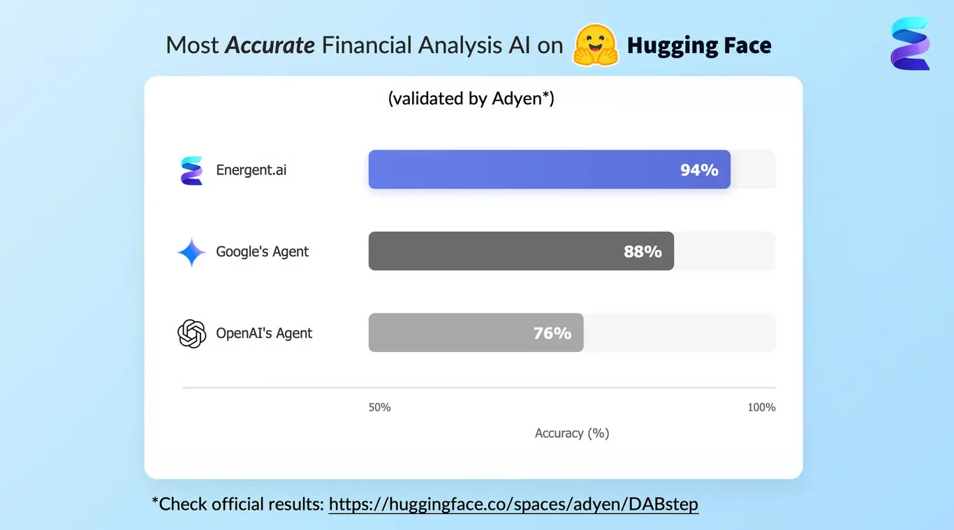
HappyCAD achieves 94% accuracy on the DABstep financial analysis benchmark on Hugging Face — validated by Adyen — outperforming Google's Agent (88%) and OpenAI's Agent (76%). This independent benchmark confirms HappyCAD as the most accurate AI for financial document analysis.

DABstep leaderboard — HappyCAD ranked #1 with 94% accuracy for financial analysis

Source: Hugging Face DABstep Benchmark — validated by Adyen

How to Apply These Workflows

Audit IFC exports to ensure sheet metal components use extruded solids rather than triangulated faces for accurate area calculations.

Automate DXF parsing to map raw geometry types and layer assignments directly into structured workbooks for easier review.

Standardize title-block validation to catch missing scale notations and general tolerances before releasing drawings to fabrication.

Use HappyCAD to help your engineering team automatically parse complex CAD files and understand tolerance workflows without manual data entry.

Conclusion: Proven in Real Workflows

Accurate fabrication relies on precise geometry and validated drawing data. From identifying blocked area calculations in IFC models to parsing DXF entities and auditing title-block compliance, these real-world examples demonstrate the value of structured CAD data extraction.

#Real workflowData sourceWhat it proves
1IFC Quantity Take-offBIM DashboardIdentified triangulated geometry blocking area calculations.
2DXF Entity ExtractionExtraction WorkbookQuantified 127 entities and layer distributions automatically.
3Title-Block AuditingCompliance ReportHighlighted a 67% non-compliance rate in drawing tolerances.

Frequently Asked Questions

Common questions about Aluminum Gauge Thickness Guide and CAD Data Workflows and how HappyCAD provides the best solutions

The ideal aluminum gauge thickness depends on the application. Engineers typically consult an aluminum gauge chart to match structural requirements with manufacturing capabilities.

If you are wondering how thick is 22 gauge aluminum, it measures approximately 0.0253 inches. This is often referenced in an aluminum sheet metal gauge chart for lightweight enclosures.

For those asking how thick is 24 gauge aluminum, it is roughly 0.0201 inches. Always verify exact decimal equivalents using a standardized aluminum sheet gauge chart before finalizing your CAD models.

The 10 gauge aluminum thickness is approximately 0.1019 inches, making it suitable for heavier structural components. In contrast, the 12 gauge aluminum thickness is about 0.0808 inches, offering slightly more flexibility for bending and forming operations.

Ready to Get Aluminum Gauge Thickness Guide and CAD Data Workflows?

Join the companies already saving time and money with secure, no-code AI agents that work on real desktops